
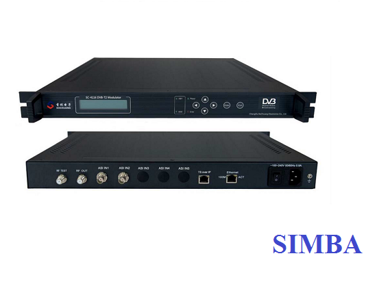
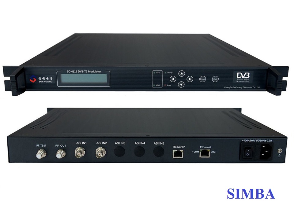
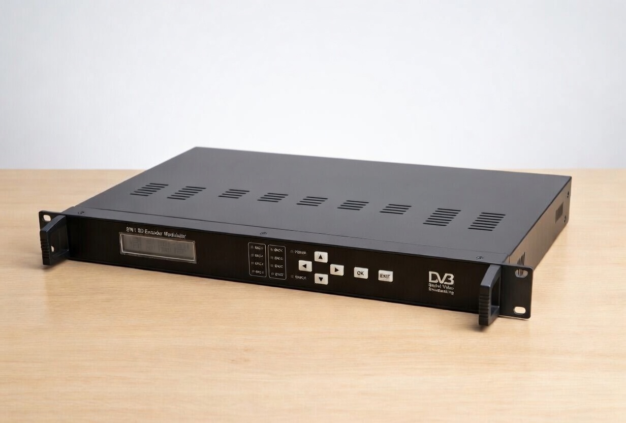
Bộ Điều Chế DVB-T2 SC-4116
SC4116-DVB-T2 Modulator complying with DVB-T2(EN302 755) standard, it supports 1×ASI, 1×IP input and 1×DVB-T2 RF output, with its advanced modulating, this modulator can effectively make use of the ground spectrum resources and make it is possible to provide reliable signals for fixed, mobile and portable devices, which allows it to be widely used in setting up digital broadcasting network and suitable for HFC broadband digital MMDS system.
FEATURES
-
Comply with DVB-T2(EN302 755) standard
-
FFT: 1K,2K,4K,8K
-
Bandwidth: 5M,
-
MER: ≥ 42db
-
Frequency Range: 36~900MHz, 1Khz step
-
Signal real-time monitor
-
LCD/Keyboard control by front panel and network management by Ethernet
|
Input Interface |
ASI (choose by manual) |
DVB standard, BNC interface |
|
IP (choose by manual) |
100mbps RJ45,1*TS over UDP Multicast |
|
|
Modulation Output |
RF |
F-head; Impedance 75Ω; |
|
Standard |
DVB-T2 (EN302 755 ) |
|
|
FFT Mode |
1K,2K, 4K,8K |
|
|
Bandwidth |
|
|
|
Constellation |
QPSK, 16QAM, 64QAM, 256QAM |
|
|
Guard Interval |
1/128, 1/32, 1/16, 19/256, 1/8, 19/128, 1/4 |
|
|
FEC Rate |
1/2, 3/5, 2/3, 3/4, 4/5, 5/6 |
|
|
Output Level ATT |
-26dbm~+3dbm (0.1db step) |
|
|
|
36~900MHz, 1Khz step |
|
|
MER |
≥ 42db |
|
|
Control |
IP remote |
NMS ( |
|
Front panel |
Keyboard + LCD |
|
|
General Features |
Size |
|
|
|
0~ |
|
|
Power |
100-240VAC, 50Hz, 25W |
ASI Interface
Input Interface: 2×ASI, DVB standard
Connector: BNC
Impedance: 75Ω
TS package format: 188/204bytes (automatic identification)
Ethernet Port: IEEE802.3 Ethernet, RJ45
Software Protocol: IP/UDP
RF Output
Connector: F-head
Impedance: 75Ω
Frequency Range: 36MHz~900MHz
Connector: F-head
Impedance: 75Ω
Modulation Mode: QPSK, 16QAM, 64QAM,256QAM
Channel Coding: DVB Standard, RF Coding
MER: ≥42dB
Network Interface
Ethernet Port: IEEE802.3 Ethernet, RJ45
Software Protocol: UDP
Conforms to GB13837-92 & GB8898-88
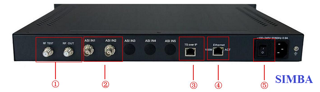
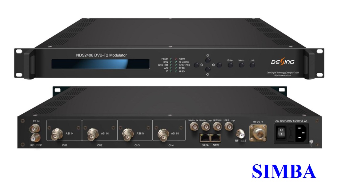
|
1 |
RF Output and RF Test Output |
|
2 |
ASI IN |
|
3 |
IP IN |
|
4 |
Ethernet Port |
|
5 |
Power Switch |
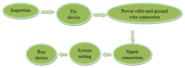
Installation Preparation
Please install as bellow steps:
- Check possible lose or damage of the device during transportation
- Prepare a suitable environment for installation
- Install the device
- Signal cable connection
Each tiny step will be mentioned in this chapter. Please refer to rear panel for specific location.
Installation Procedure
Environment Requirement
|
Project |
Requirement |
|
|
Room Space |
When installing multi-row of racks, please make the distance 1.2~1.5M between front door and back door, and the distance 0.8M between rack and wall. |
|
|
Room Floor |
Non-conducting, dust-free Ground anti-static material volume resistivity: 1×10⁷-1×10¹⁰W, ground current-limiting resistance: 1MW, floor bearing weight: >450Kg/m2 |
|
|
Temperature |
Long-term operation: 5~40ºC, short-term operation: 0~45ºC, air-conditioner is a good option. |
|
|
Relative Humidity |
Long-term operation: 20%~80%, short-term operation: 10%-90% |
|
|
Ambient Pressure |
86-105KPa |
|
|
Doors and Windows |
Seal by dust-prevention rubber strip, double glass is a good option for window and seal it tightly. |
|
|
Fire Requirement |
Automatic fire alarm system and hand-held fixed fire extinguish system are required. |
|
|
Power Requirement |
3 stand alone power supply system for equipment, air-conditioner, and lighting. Alternating current power supply for equipment (220V, 50Hz, 24.2W). Please check before running the device. |
|
-
Good ground wire design is the base of the whole system, and is essential to lightning protection and anti-interference. The system must follow above principles.
-
Keep good electrical contact between both ends of outer conductor and shielding layer and the appearance of metal case of the connected device.
-
Make sure that connections of both ends of the ground wire are with good electrical contact and prepare for corrosion prevention treatment.
-
Do not use other device for ground wire electrical connection.
-
The sectional area of ground wire from rack connecting to anti-thunder unit must be greater than or equal to 25mm2
-
Power jack is on the left of rear panel, power switch is at the left side of power jack, and ground connecting screw is at the lower left side of power jack.
-
Connecting power cable: put one end of the cable into the AC power jack and the other (power plug) to the AC power supply.
-
Connecting ground wire: when connecting alone to protective area in the room, you can use independent ground or common ground with other equipments (like transmission equipment) with a resistance less than 1.
Before operating, user should connect all devices requiring cables.
-
When keyboard is locked, press any key to make LCD active, and then press “enter”, and then “exit” to unlock the keyboard to enter the main menu.
-
After 60 seconds without any operation, the keyboard automatically locks.
-
When keyboard it locked, press any key to make LCD active, and then press up key to check device version number, down key to check IP address, right key to check MAC address.
-
For numerical value modification, press “enter” key to active the cursor, then move cursor to the specific location, press “up or down” key to change the value, press enter key again to confirm parameter modification.
- Input Info.
- System Setting
- RF Setting
- IP Input
- Network Setting
- Save Config
- Load Config
- Version
- Language
- Error Info.
- Program Total 00
List Empty
-
2.1. Input Mode
-
2.2. Fec Mode
-
2.3. Rotation
-
2.4. Modulation
-
2.5. Coderate
-
2.6. Guard interval
-
2.7 Bandwidth
-
2.8 Pilotmode
-
2.9 FFT Mode
-
2.10 L1 Modulation
-
2.11 NIT
Input Mode
Move the cursor to “Input Mode” and enter into it. Then it shows as below (Press ‘up or down’ key to choose menu, then press the ‘enter’ key to confirm):
-
2.1. Input Mode
-
2.2. FEC Mode
-
2.3. Rotation
-
2.4. Modulation
-
2.5. Baudrate
Move the cursor to “Guard Interval” and enter into it. Then it shows as below (Press ‘up or down’ key to choose menu, then press the ‘enter’ key to confirm):
- 2.6. Guard Interval
- 2.7. Bandwidth
Move the cursor to “Pilotmode” and enter into it. Then it shows as below (Press ‘up or down’ key to choose menu, then press the ‘enter’ key to confirm):
- 2.8. Pilotmode
- 2.9. FFT Mode
- 2.10. L1 Modulation
-
2.11. NIT
- 3.1. Frequency
- 3.2. Output Power
- 3.3. Modulator Enable
- 3.1. Frequency
786.000 MHz
-
3.2. Output Power
Modulator Enable
- 3.4. Modulator Enable
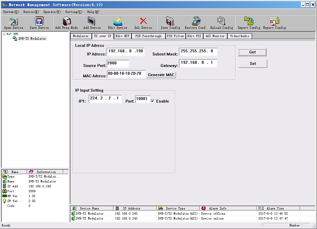
- 4.1 Destination IP
- 4.2 Destination Port
- 4.3 Subnet Mask
- 4.4 Gateway
- 4.5 Local IP
- 4.6 Local MAC
- 4.7 Local Port
- 4.1 Destination IP
- 4.2 Destination Port
- 4.3 Subnet Mask
- 4.4 Gateway
- 4.5 Local IP
- 4.6 Local MAC
-
4.7 Local Port
- 5.1. IP Address
- 5.2. Subnet Mask
- 5.3. Gateway
- 5.4. NMS UDP Port
- 5.5. MAC Address
- 5.1 IP Address
- 5.2 Sub Mask
- 5.3 Gateway
- 5.4 NMS UDP Port
- 5.5 MAC Address
Move the cursor to “save config” and enter into it. Then it shows as below:
- 6. Save Config
- 7.1. Reload Config
- 7.2. Restore Config
- 7.1. Reload Config
- 7.2. Restore Config
7. Version
- 8. Language
Move the cursor to “error info.” and enter into it. It shows as below:
- 9. Error Info.
There are 2 LED indicators on the panel:
-
“POWER” is power indicator. When switch on, it’s green, which indicates device works well.
-
“ERROR” indicates error status when it’s red.
7.3.2.1 “POWER” is Off
NMS Operation Guide
 on a PC to set and monitor device. Most of all head-end equipments (satellite receiver, encoder, multiplexer, scrambler, modulator, and adapter, etc.) can be set by NMS which is with UDP protocol and supports windows operation system.
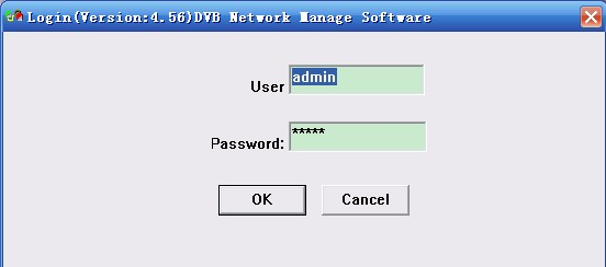

|
I: Menu Bar |
IX: Restore Config |
|
II: Open Device |
X: Reload Config |
|
III: Save Device |
XI: Import Config |
|
IV: Add Freq Node |
XII: Export Config |
|
V: Add Device |
XIII: Device List |
|
VI: Edit Device |
XIV: Device Connection Info |
|
VII: Del Device |
XV: Device Config Operation |
|
VIII: Save Config |
XVI: Alarm List |
Below chapters will introduce above functions separately.
“Open Device” & “Save Device”: open saved config and save current config. If the config and the NMS are in the same file, they can automatically run when opening or closing the network management software.
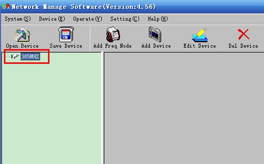
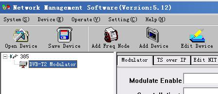
Add Frequency
“Add Frequency”: all devices can be divided and managed by frequency. Click “Add Freq Node”, then a dialog for adding frequency shows up. Input a frequency, like 385MHZ”, and then click “OK” to confirm:
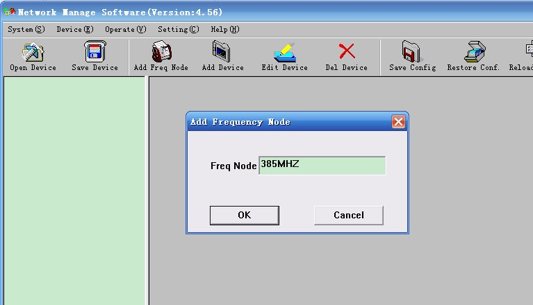
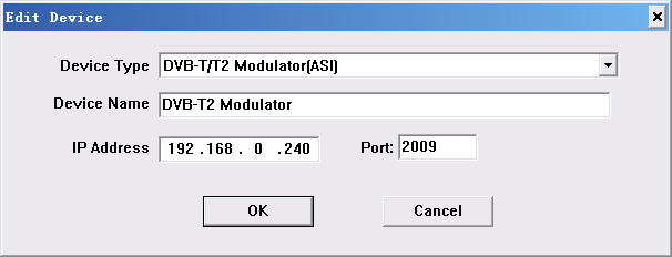
Add device under the frequency. Choose frequency and then click “Add Device”, then below dialog shows up:
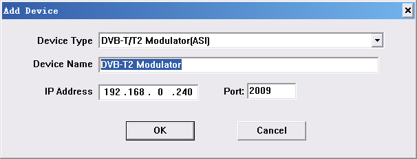
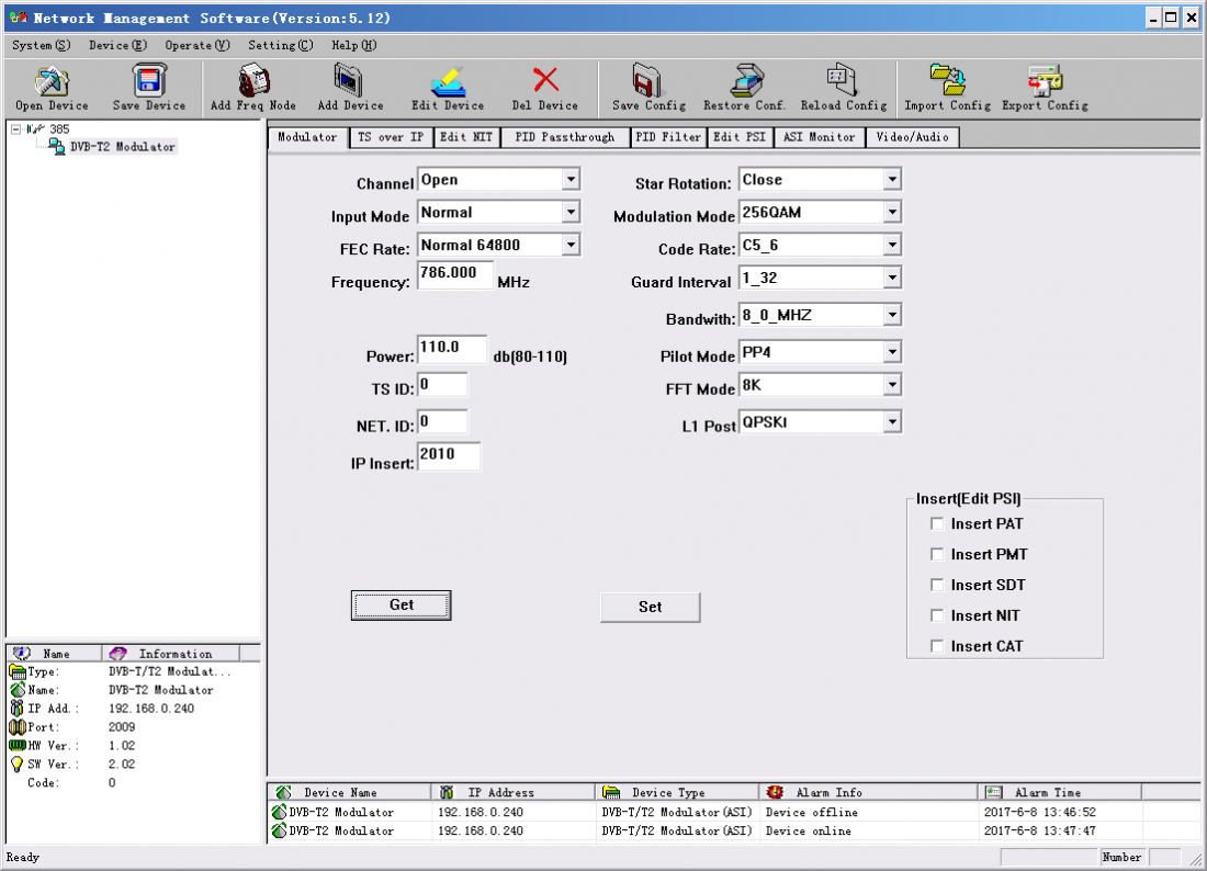
Choose device type “DVB-T/T2 Modulator(ASI)”, set device name (you can name as you like), and set IP address and Port of the device. You can check IP address by clicking down key on the panel or you can enter into “Network Setting” in the menu to check it. Default IP address and Port for DVB-T2 Modulator are 192.168.000.240 and 2009.
| Encoder | 192.168.0.110:2010 |
| 4IN1 Encoder | 192.168.0.210:2010 |
| Multiplexer | 192.168.0.120:2010 |
| 2-Out Multiplexer | 192.168.0.210:2010 |
| 7IN1 Satellite Receiver | 192.168.0.020:2010 |
| Scrambler | 192.168.0.130:2010 |
| 4-Channel Satellite Receiver | 192.168.0.050:2010 |
| QAM Modulator | 192.168.0.040:2010 |
| DTMB-T Modulator: | 192.168.0.040:2010 |
| QPSK Modulator | 192.168.0.140:2010 |
| DS3 Adapter | 192.168.0.150:2010 |
| TS-IP Gateway | 192.168.0.254:2010 |

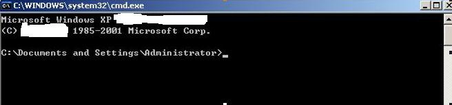
After entering into it:
Input “arp –d” to clear old “arp” information:
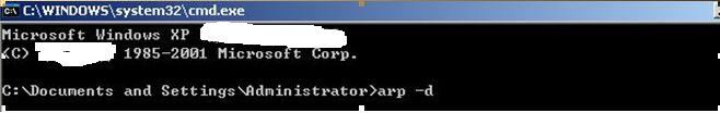
Input “PING”:
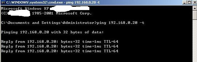
Here the ping is 192.168.0.20 (you can put your device IP address when you do it). Here we found 192.168.0.20 passed, which means there is already a device with 192.168.0.20. Then we can find the device out and modify the IP address of the device or your device.
After shooting the problem, the icon turns 
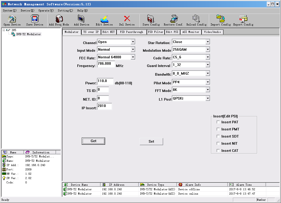
At the device list column, click device name to check it. Check the basic info (like firmware and software version) at the device connection column and edit it at the right device operation area.
“Del Device”: delete the device you don’t need from the device list.
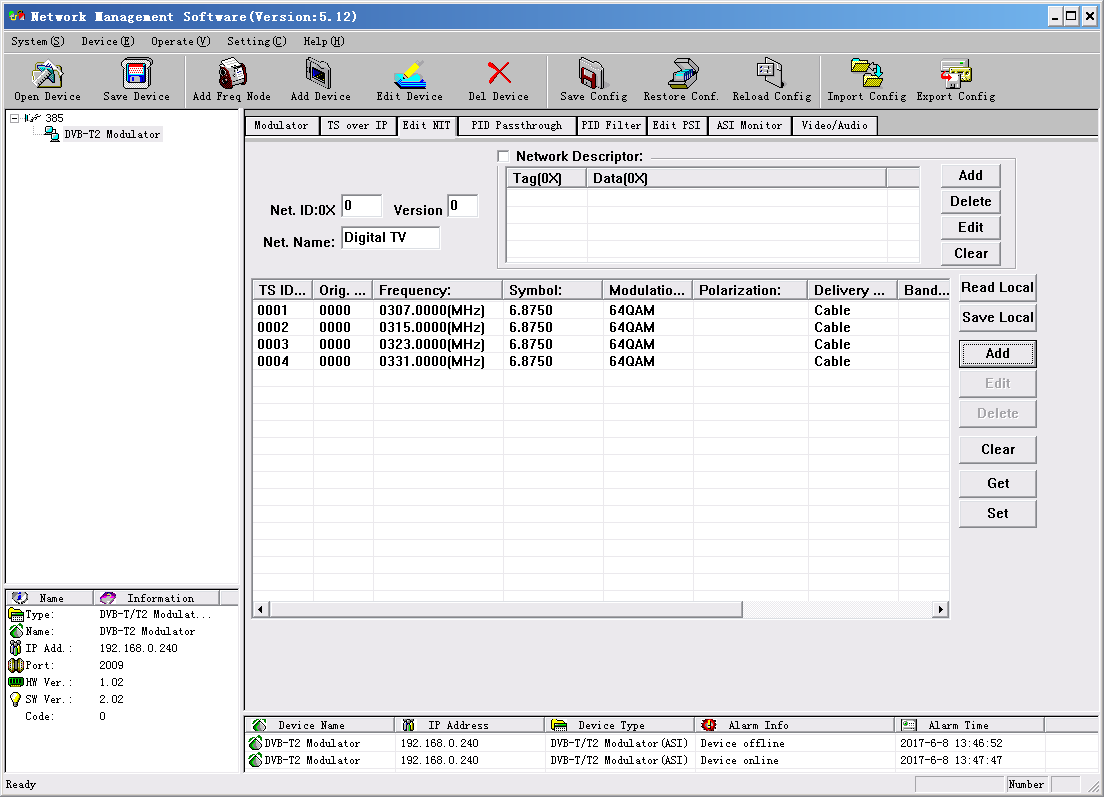
Check and Set Config
Note: user had better do the following operation before configuring the device:
Click  button in NMS software, then click
  button to clear the old parameter.
TS over IP


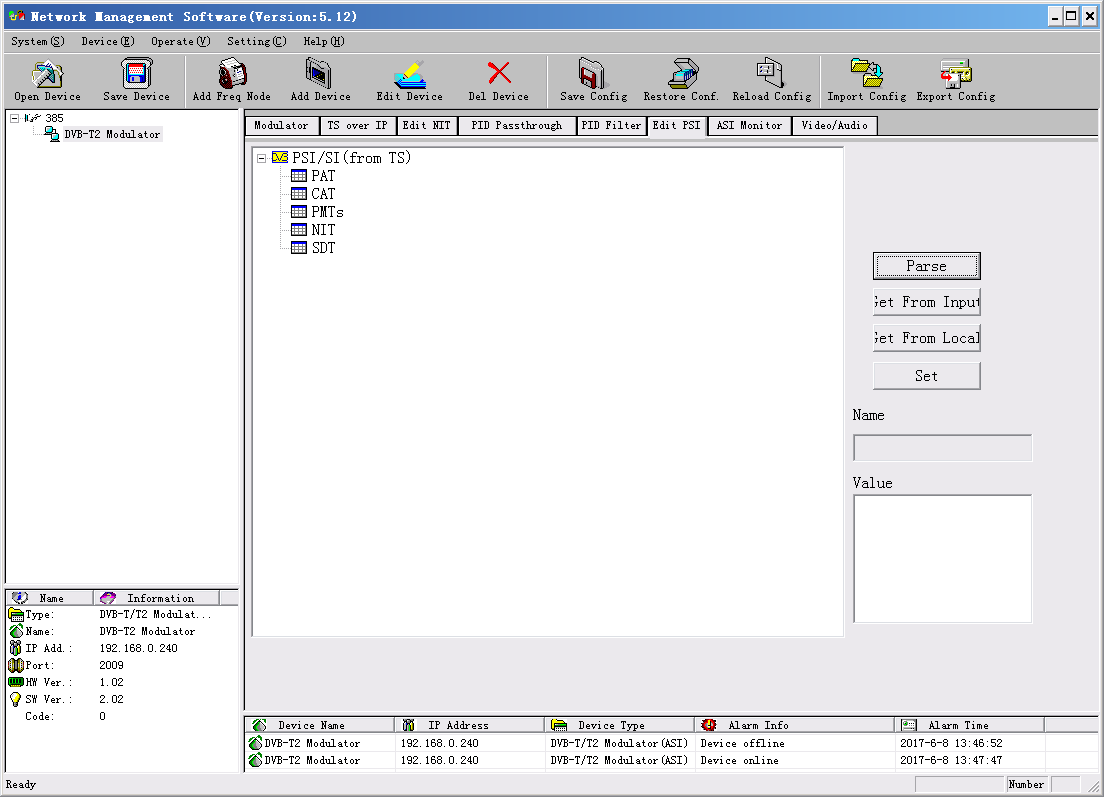
Edit PSI
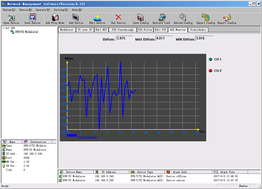
ASI Monitor
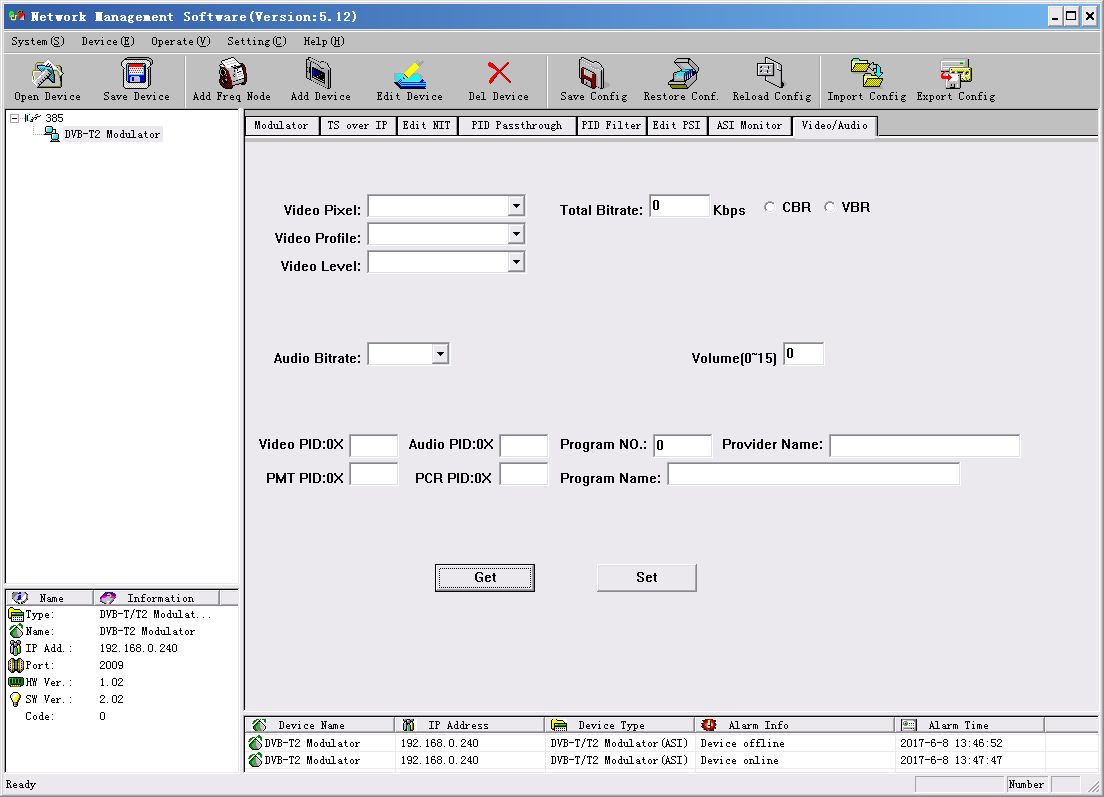
Video/Audio


First please choose the config you want to import, and click “Erase” to clear current config and then import config from FLASH. At this moment, the config cannot be used. You need restart the device or click “Reload Config” to start new config.

- Digital Headend
- DVB-T2 Solution
- Resort & Hotel & Building CATV System
Sản phẩm cùng loại
Tin Tức Sản phẩm
- Khuếch đại truyền hình cáp SCTV
- Cáp đồng trục
- Cáp mạng
- Khuếch đại
- Bộ chia
- Bộ chèn nguồn / Chia điện
- Tap-off
- Đầu nối / Jack F
- Bộ điều chế
- Bộ giải điều chế
- Bộ trộn tín hiệu
- Bộ ghép tín hiệu
- Bộ thu tín hiệu
- RF Switch
- Encoder-Modulator
- MUX-Scrambler
- Suy Hao-Bộ Lọc Tín Hiệu
- POI / MU / RU
- Feeder Cable
- IBS Connector
- IBS Adapter
- IBS Splitter
- Directional Coupler
- Hybrid Coupler
- IBS Combiner
- Antenna
- Jumper / Attenuator
- Termination / Dummy Load
- Duplexer / Filter
- Thiết bị khác
- Ghi luồn kéo cáp
- Máy đo tín hiệu truyền hình
- Tủ nguồn
- Tủ thiết bị
- Máy đo tín hiệu quang
- Ty / Tán
- Đo tín hiệu mạng
- Kẹp cáp 2 rãnh 3 lổ
- Máy hàn quang
- Túi đựng đồ nghề
- Dao cắt sợi quang
- Đồ bảo hộ lao động
- Dao bóc vỏ cáp
- Dây buộc bọc nhựa
- Dao tách dây treo
- Kìm thi công
- Dây đai inox
- Tool cáp QR540
- Sắt V
- Thang nhôm rút gọn
- Móc J
- Dụng cụ khác
- Giá quấn cáp
- Gông treo cáp / Collier
- Bảng tài sản
- Thanh quản lý cáp
- Dây rút
- Bộ treo néo cáp
- Ống co nhiệt
- Sào thi công
- P.1901, TN Saigon Trade Center, Số 37 Tôn Đức Thắng, P. Sài Gòn, TP.HCM
- +84 028 62805439
- 0902 745768
- info@simbacorp.com.vn - infosimbacorp@gmail.com
- Xem bản đồ
- 132 Đường Số 6, P. Long Trường, TP.HCM
- 0902 745768
- 0906 634768
- info@simbacorp.com.vn - infosimbacorp@gmail.com
- Xem bản đồ

GPKD số : 0312218379 cấp ngày 03-04-2013 bởi Sở Kế hoạch và Đầu Tư TP.Hồ Chí Minh.
NĐD : Trương Quốc Cường.

