
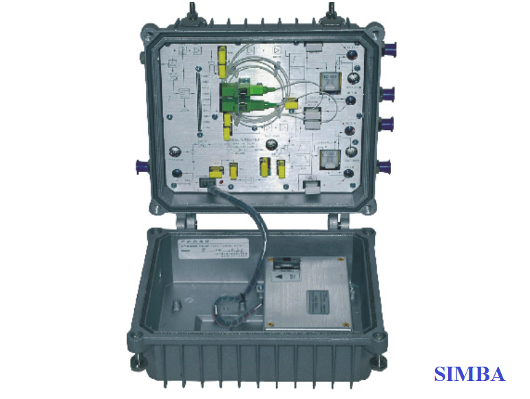
Node Quang 1GHz WR1004DM is our new high-class 4-way output CATV network optical receiver. The pre-amplifier adopts all-GaAs MMIC, post-amplifier adopts GaAs module.
Optimized circuit design, coordinate with our 10 years design experience, the device achieve high performance index.
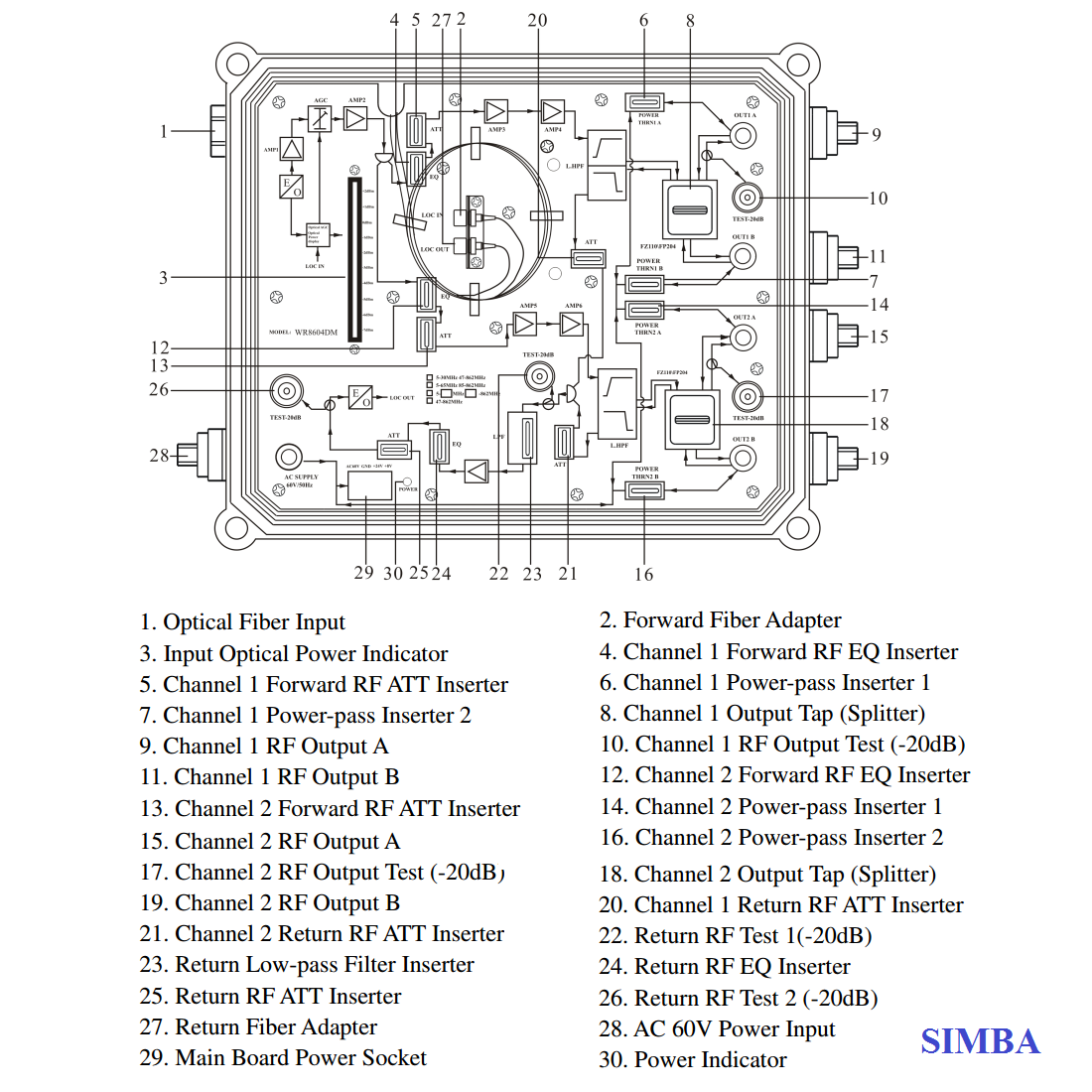
The adjustment of RF attenuation and equalization both adopts fixed attenuator inserter that makes the engineering debug very convenience.
It is the main equipment to build CATV network
FEATURE
-
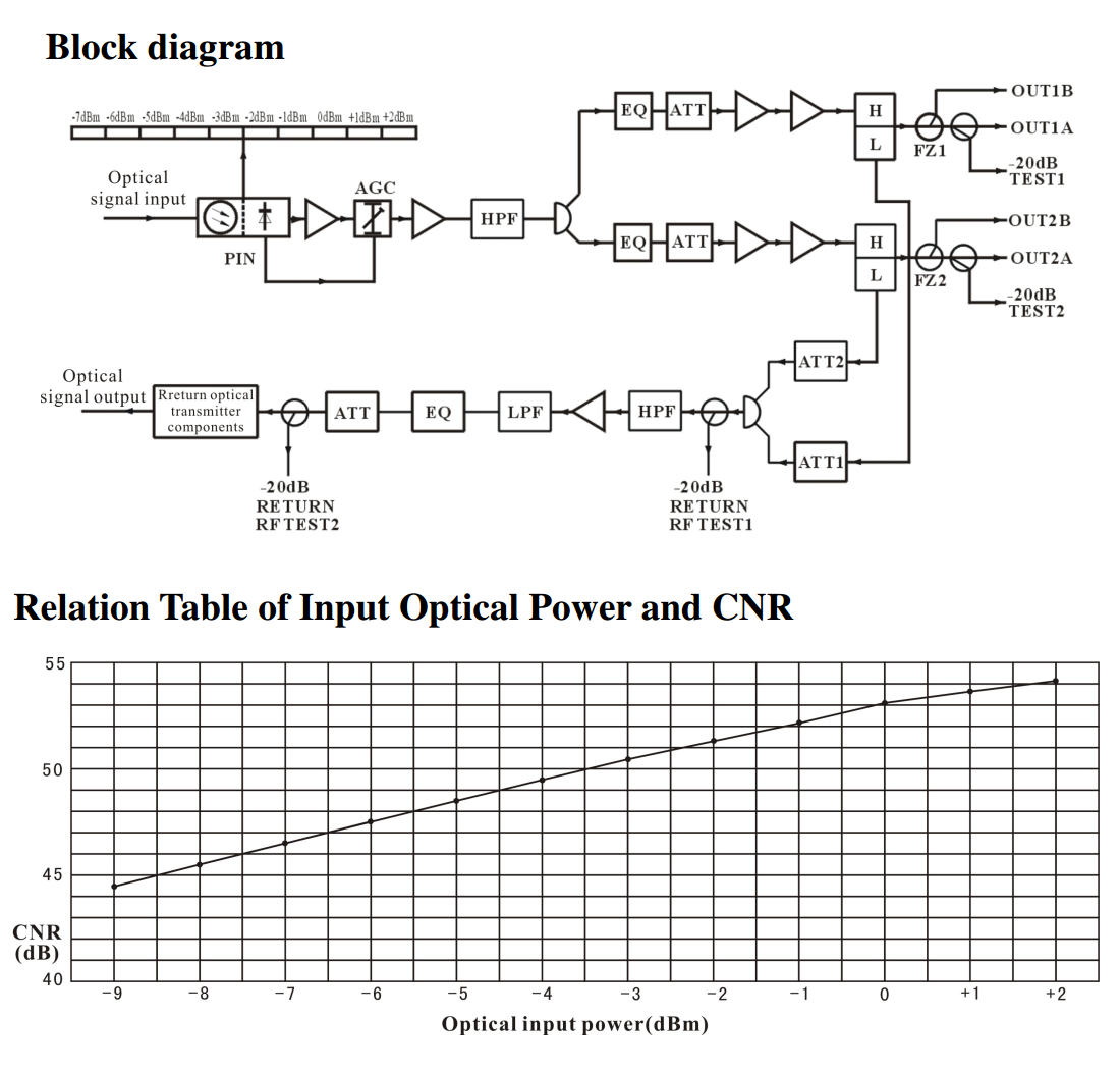
Optical AGC control, when input optical power is -7~+2dBm, the output level, CTB, CSO basically unchanged.
-
10 bar LED optical power instructions, more accurately display the optical power.
-
Optimized circuit design, the pre-stage adopts SMT processing, while post-stage adopts module amplify typical circuit, which make the RF signal linear more prefect.
-
The adjustment of RF attenuation and equalization both adopts fixed attenuator inserter. EQ position insert ATT inserter can change the equilibrium, so the engineering debug is very convenient.
-
Power doubler output, high gain and low distortion.
-
The forward path adds a high-pass filter, while the return path adds a high-pass filter and a low-pass filter, which effectively extend the NPR dynamic range of uplink.
-
Return emission can select burst mode to sharply decrease the noise convergence and reduce the forepart receiver number.
The performance parameters of this manual according to the measuring method of GY/T 194-2003 <Specifications and methods of measurement on optical node used in CATV systems>, and tested in the following conditions.
Testing conditions:
1. Forward optical receive part: with 10km standard optical fiber, passive optical attenuator and standard optical transmitter composed the testing link. Set 59 PAL-D analog TV channel signal at range of 45/87MHz~550MHz under the specified link loss. Transmit digital modulation signal at range of 550MHz~862/1003MHz, the digital modulation signal level (in 8 MHz bandwidth) is 10dB lower than analog signal carrier level. When the input optical power of optical receiver is -1dBm, the RF output level is 108dBµV, with 6dB output tilt, measure the C/CTB, C/CSO and C/N.
2. Return optical transmit part: Link flatness and NPR dynamic range are the link indexes which is composed of backward optical transmitter and backward optical receiver. Note: When the rated output level is the system full configuration and the receiving optical power is -1dBm, equipment meets the maximum output level of link index. When the system configuration degrade (that is, actual transmission channels reduce), the output level of equipment will be increased.
Friendly Notice: Suggest you setting the RF signal to 6~9dB slope output in the practical engineering
application to improve the nonlinear index (behind the node) of the cable system.
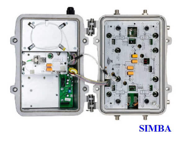
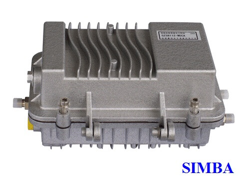
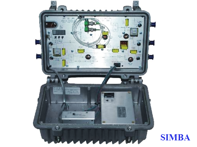
Node Quang 1GHz WR1004DM
Structure Diagram
| Item | Unit | Technical Parameter | |
| Forward Part | |||
| Optical Parameter | |||
| Receive Optical Power | dBm | -7 ~ +2 | |
| Optical Return Loss | dB | >45 | |
| Optical Receiving Wavelength | nm | 1100 ~ 1600 | |
| Connector Type | FC/APC, SC/APC or specified by the user | ||
| Fiber Type | Single Mode | ||
| Link Parameter | |||
| C/N | dB | ≥51 (-1dBm input) | |
| C/CTB | dB | ≥65 | EQ 6dB, Output level 108dBμV |
| C/CSO | dB | ≥60 | |
| RF Parameter | |||
| Frequency Range | MHz | 45~862/1003 (or specified by the user) | |
| Flatness in Band | dB | ±0.75 | |
| Fixed slope | dB | 2±0.5 | |
| Rated Output Level | dBμV | ≥ 108 | |
| Max Output Level | dBμV | ≥110 | |
| Output Return Loss | dB | ≥14 | |
| Output Impedance | Ω | 75 | |
| Fixed ATT and EQ (common use) | dB | 2.3.4.5.6.7.9.13 (or specified by the user) | |
| Return Part | |||
| Optical Parameter | |||
| Optical Transmit Wavelength | nm | 1310±10, 1550±10 or specified by the user | |
| Output Optical Power | mV | 0.5, 1, 2 | |
| Optical Connector Type | FC/APC, SC/APC or specified by the user | ||
| RF Parameter | |||
| Frequency Range | MHz | 5~65 (or specified by the user) | |
| Flatness in Band | dB | ±1 | |
| Input Level | dBμV | 72~85 | |
| Output Impedance | Ω | 75 | |
| General Performance | |||
| Power Voltage | V | A: AC (150~265)V, B: AC (35~90)V | |
| Operating Temperature | ℃ | -40~60 | |
| Storage Temperature | ℃ | -40~65 | |
| Relative Humidity | % | (-9dBm/-8dBm/-7dBm/-6dBm/-5dBm/-4dBm) — (+2dBm) adjustable | |
| Consumption | VA | ≤30 | |
| Dimension | mm | 240 (L)×240 (W)×150 (H) | |
| Burst Mode (Select this mode, see below) | |||
| Optical Output Power (Close the burst mode) | dBm | -30 | |
| Laser Turn On Threshold | dBμV | ≥70 | |
| Laser Turn Off Threshold | dBμV | ≤62 | |
| Laser Turn On Time (t1) | us | 0.5 ≤ t1 ≤ 1 | |
| Laser Turn Off Time (t2) | us | 0.5 ≤ t2 ≤ 1.5 | |
Common Failure Analysis and Troubleshooting:
| Failure phenomenon | Failure cause | Solution |
| After connecting the network, the image of the optical contact point has obvious netlike curve or large particles highlights but the image background is clean. | 1. The optical input power of the optical receiver is too high, make the output level of the optical receiver module too high and RF signal index deteriorate. 2. The RF signal (input the optical transmitter) index is poor. |
1. Check the optical input power and make appropriate adjustments to make it in the specified range; or adjust the attenuation of optical receiver to reduce the output level and improve index. 2. Check the front end machine room optical transmitter RF signal index and make appropriate adjustments. |
| After connecting the network, the image of the optical contact point has obvious noises. | 1. The optical input power of the optical receiver is not high enough, results in the decrease of C/N. 2. The optical fiber connector or adapter of the optical receiver has been polluted. 3. The RF input signal level of the optical transmitter is too low, make the modulation degree of the laser is not enough. 4. The C/N index of system link signal is too low. |
1. Check the received optical power of the optical contact point and make appropriate adjustments to make it in the specified range. 2. Improve the optical received power of the optical contact point by cleaning the optical fiber connector or adapter etc methods. Specific operation methods see “Clean and maintenance method of the optical fiber connector”. 3. Check the RF input signal level of the optical transmitter and adjust to the required input range. (When the input channels number less than 15, should be higher than the nominal value.) 4. Use a spectrum analyzer to check the system link C/N and make appropriate adjustments. Make sure the system link signal C/N﹥51dB. |
| After connecting the network, the images of several optical contact points randomly appear obvious noises or bright traces. | The optical contact point has open circuit signal interference or strong interference signal intrusion. | 1. Check if there is a strong interference signal source; change the optical contact point location if possible to avoid the influence of the strong interference signal source. 2. Check the cable lines of the optical contact point, if there is shielding net or situation that the RF connector shielding effect is not good. 3. Tightly closed the equipment enclosure to ensure the shielding effect; if possible add shielding cover to the optical contact point and reliable grounding. |
| After connecting the network, the images of several optical contact points appear one or two horizontal bright traces. | Power supply AC ripple interference because of the bad earth of equipment or power supply. | Check grounding situation of the equipment, make sure that every equipment in the line has been reliably grounding and the grounding resistance must be﹤4Ω. |
| After connecting the network, the received optical power of the optical contact point is unstable and changes continuously. The output RF signal is also unstable. But the detected optical output power of the optical transmitter is normal. | The optical fiber connector types do not match, maybe the APC type connect to PC type. The optical fiber connector or adapter may be polluted seriously or the adapter has been damaged. | 1. Check the type of optical fiber connector and adopt the APC type optical fiber connector to ensure the normal transmission of optical signal. 2. Clean the polluted optical fiber connector or adapter. Specific operation methods see “Clean and maintenance method of the optical fiber connector”. 3. Replace the damaged adapter. |
Clean and maintenance method of the optical fiber active connector:
In many times, we consider the decline of the optical power as the equipment faults, but actually it may be caused by that the optical fiber connector was polluted by dust or dirt. Inspect the fiber connector, component, or bulkhead with a fiberscope. If the connector is dirty, clean it with a cleaning technique following these steps:
1. Turn off the device power supply and carefully pull off the optical fiber connector from the adapter.
2. Wash carefully with good quality lens wiping paper and medical absorbent alcohol cotton. If use the medical absorbent alcohol cotton, still need to wait 1~2 minutes after wash, let the connector surface dry in the air.
3. Cleaned optical connector should be connected to optical power meter to measure output optical power to affirm whether it has been cleaned up.
4. When connect the cleaned optical connector back to adapter, should notice to make force appropriate to avoid china tube in the adapter crack.
5. The optical fiber connector should be cleaned in pairs. If optical power is on the low side after clean, the adapter may be polluted, clean it. (Note: Adapter should be carefully operated, so as to avoid hurting inside fiber.
6. Use compressed air or degrease alcohol cotton to wash the adapter carefully. When use compressed air, the muzzle aims at china tube of the adapter, clean the china tube with compressed air. When use degrease alcohol cotton, insert directions need be consistent, otherwise can’t reach a good clean effect.
Node Quang 1GHz WR1004DM
- AM CATV
- Digital CATV
- DBS & MMDS
- FTTx PON
Sản phẩm cùng loại
Tin Tức Sản phẩm
- Khuếch đại truyền hình cáp SCTV
- Cáp đồng trục
- Cáp mạng
- Khuếch đại
- Bộ chia
- Bộ chèn nguồn / Chia điện
- Tap-off
- Đầu nối / Jack F
- Bộ điều chế
- Bộ giải điều chế
- Bộ trộn tín hiệu
- Bộ ghép tín hiệu
- Bộ thu tín hiệu
- RF Switch
- Encoder-Modulator
- MUX-Scrambler
- Suy Hao-Bộ Lọc Tín Hiệu
- POI / MU / RU
- Feeder Cable
- IBS Connector
- IBS Adapter
- IBS Splitter
- Directional Coupler
- Hybrid Coupler
- IBS Combiner
- Antenna
- Jumper / Attenuator
- Termination / Dummy Load
- Duplexer / Filter
- Thiết bị khác
- Ghi luồn kéo cáp
- Máy đo tín hiệu truyền hình
- Tủ nguồn
- Tủ thiết bị
- Máy đo tín hiệu quang
- Ty / Tán
- Đo tín hiệu mạng
- Kẹp cáp 2 rãnh 3 lổ
- Máy hàn quang
- Túi đựng đồ nghề
- Dao cắt sợi quang
- Đồ bảo hộ lao động
- Dao bóc vỏ cáp
- Dây buộc bọc nhựa
- Dao tách dây treo
- Kìm thi công
- Dây đai inox
- Tool cáp QR540
- Sắt V
- Thang nhôm rút gọn
- Móc J
- Dụng cụ khác
- Giá quấn cáp
- Gông treo cáp / Collier
- Bảng tài sản
- Thanh quản lý cáp
- Dây rút
- Bộ treo néo cáp
- Ống co nhiệt
- Sào thi công
- P.1901, TN Saigon Trade Center, Số 37 Tôn Đức Thắng, P. Bến Nghé, Q1, TP.HCM
- +84 028 62805439
- 0902 745768
- info@simbacorp.com.vn - infosimbacorp@gmail.com
- Xem bản đồ
- 661F Đỗ Xuân Hợp, P. Phước Long B, Q9, TP.HCM
- 0902 745768
- 0906 634768 - 0916 062245
- info@simbacorp.com.vn - infosimbacorp@gmail.com
- Xem bản đồ

GPKD số : 0312218379 cấp ngày 03-04-2013 bởi Sở Kế hoạch và Đầu Tư TP.Hồ Chí Minh.
NĐD : Trương Quốc Cường.